Standard Transthoracic Echocardiogram: Complete Imaging Protocol
The standard transthoracic echocardiographic examination
This chapter presents a sequential series of images that comprise a complete standard echocardiographic examination. The image views are discussed in the same sequential order that they are usually obtained during the examination.
Measurement techniques
Measuring dimensions
Chamber dimensions constitute key parameters of most echocardiographic examinations. For example, left ventricular size, measured as its inner diameter, is strongly related to heart failure, ventricular tachyarrhythmias, and overall mortality. Ventricular dimensions are measured using an electronic caliper, with the tips positioned at the interface between the compacted myocardium and the noncompacted myocardium (i.e trabeculae). The compacted myocardium is the solid, compact wall. Thus, with regards to measuring ventricular dimensions, trabeculae and papillary muscles are considered part of the left ventricular cavity.
Other dimensions–including atrial dimensions, mitral annulus, aortic annulus, etc–are measured using the blood-tissue interface (inner edge to inner edge). The blood-tissue interface may also be used to measure ventricular dimension in instances when the interface between compacted and noncompacted myocardium cannot be discerned.
Scanning Maneuvers
It is necessary to continuously adjust the transducer in order to obtain the best possible image quality. Image optimization and requires experience, patience, and correct instrumentation settings. Technical aspects of optimization of image quality have been discussed previously (refer to Optimization of the Ultrasound Image). Additionally, a number of transducer movements can be made in order to focus on the region of interest and optimize the image. These maneuvers are tilting, rotating, sliding, rocking and angling.
Tilt: The transducer maintains the same axis orientation to the heart but moves to a different imaging plane.
Rotate: The transducer maintains a stationary position while the index marker is moved to a new position.
Slide: The transducer moves across the patient’s skin to a new position.
Rock: Within the same imaging plane, the transducer changes orientation either toward or away from the orientation marker.
Angle: The transducer is kept at the same location on the chest, and the sound beam is directed to show a new structure.
The ultrasound transducer has an orientation index marker, which is pointed differently in each echocardiographic view. A corresponding marker is shown in the ultrasound image. The index marker facilitates orientation. Any structure located to the right of the index marker will be shown on the right side of the corresponding image marker in the ultrasound image. Similarly, structures located on the left-hand side of the index marker are presented on the left side of the marker in the image.
Echocardiographic windows

The standard examination include the following four imaging windows:
- Parasternal window
- Apical window
- Subcostal window (SC)
- Suprasternal window (suprasternal notch)
Multiple views are obtained in each window. Some parameters, e.g left ventricular diameter, are evaluated in several views in order to assess the reliability and reproducibility of the measurements.
The parasternal and apical windows are obtained with the patient positioned in the left lateral decubitus position, provided that the patient is able to assume this position. The subcostal and suprasternal windows are obtained with the patient in the supine position.
Parasternal Windows
PLAX – Parasternal Long-Axis view
The parasternal long-axis view (PLAX) is located on the left side of the sternum. It provides imaging planes of the long axis of the heart. Figure 2 illustrates the position of the transducer, the orientation of the index marker and the scanning plane through the heart.

Position of the transducer: The ultrasound transducer is placed on the left sternal border. The transducer must not be placed on the sternum. The index marker points towards the patient’s right shoulder.
Optimal image quality: typically at the end-expiration.
Figure 3 illustrates the ultrasound image obtained in PLAX. The image should be obtained in the intercostal space providing the best possible image quality, largest dimension of the left ventricle and reveals the structures illustrated in Figure 3.

Schematic illustration of heart: Patrick J. Lynch, CC BY 2.5.
Structures examined in PLAX
LVOT (Left Ventricular Outflow Tract)
LVOT is the outflow tract of the left ventricle (Figure 3). The diameter of LVOT is measured at end-systole.
Aortic valve
The structure and function of the aortic valve are assessed visually. This includes the right coronary cusp (RCC), the non-coronary cusp (NCC) and coaptation of the cusps. The left coronary cusp (LCC) is not visible in PLAX. Cusp coaptation is a term describing how well the cusps align and seal the valve when closing.
Calcified aortic valves display irregular, thick cusps, with high echogenicity.
Aortic regurgitation may be visualized by positioning the color Doppler over the LVOT and the aortic valve. Aortic stenosis is examined by means of spectral Doppler.
The diameter of the aortic annulus is also measured.
Aorta
The proximal segment of the ascending aorta is visible in parasternal long-axis view. The structures that should be assessed are sinus of Valsalva, STJ (sinotubular junction) and ascending aorta. The diameters vary by sex, age, and body size.
Aortic aneurysm is defined as dilatation of the aortic root. A dilated aortic root in a patient presenting with severe chest pain should lead to suspicion of aortic dissection. Dissections may originate in the aortic root, or dissect towards the root after arising more distally. The ultrasound image may reveal an intimal flap, which consists of the dissected aortic intima (separated from the aortic wall). An intimal flap separates the aortic lumen into a true lumen (where blood flows) and false lumen (hematoma). Color or spectral Doppler typically reveals flow signals in the true lumen, but not in the false lumen. LVOT and aortic dimensions are illustrated in Figure 4.

Aortic dissection involving the aortic root typically leads to widening of the aortic root.
Left atrium
The size of the left atrium is estimated by measuring the anteroposterior diameter (Figure 4).
Left ventricle
The basal and midventricular portions of the septum and the inferolateral wall are visualized in parasternal long-axis view (the apex is not visible in PLAX). The wall motions in these regions are assessed during systole. All myocardium should thicken and travel towards the cavity during systole. The size of the ventricle is estimated by measuring its diameter; the caliper is placed just below the mitral valve tips. The angle of the caliper should be perpendicular to the longitudinal axis of the ventricle (Figure 5). The diameter is measured at end-systole and end-diastole. Comparing end-systolic and end-diastolic diameters provide a rough estimate of left ventricular function (refer to Ejection fraction).

Color Doppler may occasionally detect a VSD (ventricular septal defect), by revealing blood flow from the left ventricle to the right ventricle.
The mitral valve
The mitral valve has an anterior and posterior leaflet. Each leaflet is attached to a papillary muscle via chordae tendineae (tendinous cords). The anatomy of the mitral valve is illustrated in Figure 5.
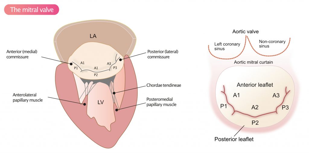
Visual assessment of leaflet mobility, coaptation and integrity of chordae tendineae and the papillary muscles is done in the 2D image. The diameter of the mitral valve (mitral annulus) is measured and the structure of the leaflets is assessed. Calcifications on the mitral valve occur, albeit less frequently than calcifications on the aortic valve.
Color Doppler allows for assessment of mitral regurgitation. The color sector should cover the mitral valve and adjacent parts of the atria and ventricles.
RVIT (Right Ventrial Inflow Tract)
In order to visualize the right heart, the transducer is tilted to allow the scanning plane to dissect the right heart. Moving the transducer to a lower intercostal space may also provide better images. The RVIT is the only view visualizing the posterior leaflet of the tricuspid valve. Leaflet coaptation is assessed. Color Doppler and pulsed wave Doppler are used to examining the tricuspid valve.
PSAX – Parasternal Short-Axis view
Position of the transducer: Same location as PLAX view, but the index marker is pointed towards the patient’s left shoulder (i.e rotated 90 degrees clockwise from PLAX).
Optimal image quality: typically at the end-expiration.
PSAX offers a cross-sectional view of the left and right ventricles (Figure 6). This view is perpendicular to the long axis of the left ventricle. A minimum of four sections through the heart are obtained in PSAX. These sections are obtained by sequentially tilting and sliding the transducer, such that the scanning planes dissect at the following levels:
- Level of the great vessels (i.e aortic plane; Figure 7)
- Mitral plane (Figure 8)
- Papillary muscles plane (Figure 9)
- Apical regions (Figure 10)

Schematic illustration of heart: Patrick J. Lynch, CC BY 2.5.
Aortic plane
Several structures can be visualized in the aortic plane (Figure 7). The aortic valve should have three cusps (NCC, RCC, LCC). A bicuspid aortic valve implies that two of the cusps have fused into one, resulting in the aortic valve having two cusps.

Color Doppler is placed over the aortic valve in order to detect signals during diastole, which suggests aortic regurgitation.
In the aortic plane, RVOT can also be assessed by Doppler (color Doppler and spectral Doppler). The color sector should embrace the RVOT, the pulmonary valve, and the pulmonary trunk. Pulsed wave Doppler (with sample volume placed 1 cm proximal to the pulmonary valve) is used to quantify pulmonary regurgitation. Color Doppler is also used to study the tricuspid valve; approximately 90% of all individuals display mild tricuspid regurgitation.
Mitral plane
By tilting the transducer caudally, the scanning plane can be directed towards the mitral valve (Figure 8). The right ventricle should be one-third of the size of the left ventricle. Left ventricular wall motion is assessed. All myocardium should thicken and travel towards the center of the cavity. Leaflet coaptation is also assessed; the leaflets should display complete coaptation, such that no color Doppler signals are seen during systole. Spectral Doppler is not used.

Papillary muscle plane
The transducer is further tilted caudally in order to visualize the papillary muscles (Figure 9). Left ventricular wall motion is assessed also in this view. No Doppler examinations are made at the papillary muscle plane.

Apex
The apex of the heart is also visualized in PSAX (Figure 10). Myocardial motion and thickening are assessed.

Apical windows
A4C: Apical Four-Chamber View
Position of the transducer: The transducer is placed on the apex of the heart, just below the breast tissue. The index marker is pointed towards the left armpit (Figure 11). This view should visualize all four chambers, the mitral valve, and the tricuspid valve (Figure 12).
Optimal image quality: typically at the end-expiration.


Schematic illustration of heart: Patrick J. Lynch, CC BY 2.5.
The left ventricle
Left ventricular dimensions, myocardial thickness and wall motion are assessed in apical four-chamber view (A4C). The entire length of the left ventricle can be visualized in A4C. It is crucial that the scanning plane provides the largest size of the left ventricle (refer to foreshortening in Left ventricular size and mass). Ventricular function is also assessed. This is usually done by calculating the ejection fraction (refer to Left ventricular systolic function).
The tricuspid valve
Valve mobility, structure, coaptation, and presence of regurgitation or stenosis are assessed. The diameter (tricuspid annulus) is measured.
The right ventricle
Wall motion is assessed using the same principles as for the left ventricle. The dimension of the right ventricle relative to the left ventricle are assessed. The three right ventricular diameters (Figure 13) are also measured. Right ventricular strain implies that the right ventricle is contracting against increased afterload, which can be caused by pulmonary hypertension, pulmonary embolism, VSD, ASD, pulmonary stenosis, etc.

The mitral valve
The mobility, structure, diameter (mitral annulus) and coaptation of the valve are assessed. Using pulsed wave Doppler, with sample volume placed just in front of the leaflet tips, the flow from the left atrium to the left ventricle is analyzed. The spectral curve reveals a biphasic flow. The first phase, denoted with the letter E, represents passive emptying of the atrium. The second phase, A, represents active emptying (atrial contraction). The ratio between E and A (E/A ratio) is used to evaluate ventricular relaxation (compliance). The less compliant the left ventricle, the larger A becomes, such that E/A ratio is increased in situations with reduced ventricular relaxation. E/A ratio has become a key parameter in the assessment of diastolic function (refer to Assessment of left ventricular diastolic function)
For VTI (velocity time integral) measurements, the sample volume is placed in the valve orifice.
In case of mitral regurgitation, continuous wave Doppler is placed in the vena contracta.
AV plane mobility
The entire AV plane should travel towards the apex during systole. During diastole, the left ventricle relaxes, and the AV plane recoils back to its starting position.
LVOT
Aortic regurgitation is examined with color Doppler. Velocities are quantified with spectral Doppler.
Apical Five-Chamber view (A5C)
Position of the transducer: Starting from A4C, the transducer is tilted a few degrees upwards, which reveals the aortic valve (the fifth chamber; Figure 14).
Optimal image quality: typically at the end-expiration.
This view provides additional opportunities for performing measurements in the LVOT, aortic valve and aortic root. Color Doppler is used in the LVOT, aortic valve and proximal aorta. Pulsed wave Doppler is directed towards the aortic annulus, with sample volume placed 1 cm proximal to the annulus. Continuous wave Doppler is used to quantifying aortic stenosis or aortic regurgitation.

A2C: Apical Two-Chamber View
Position of the transducer: Starting from A4C the transducer is rotated 30° counterclockwise. As shown in Figure 15, the left ventricle and left atrium, as well as the mitral valve, are visualized. With regards to the left ventricle, the anterior wall and the inferolateral wall are seen.
Optimal image quality: typically at the end-inspiration.
Left ventricular dimension and mobility are assessed. Leaflet coaptation, presence of mitral valve regurgitation is also assessed. In the case of regurgitation or stenosis, continuous wave Doppler is used to measuring velocities.
Schematic illustration of heart: Patrick J. Lynch, CC BY 2.5.
A3C: Apical Three-Chamber View
Position of the transducer: Starting from A2C, rotate 30 degrees counterclockwise until the aortic valve and LVOT are visible. Additional measurements are made of the abovementioned dimensions and structures (Figure 15).
Optimal image quality: typically at the end-inspiration.

Subcostal view (SC)
The subcostal view is obtained with the patient in the supine position
Position of the transducer: The transducer is placed, with the index marker pointing towards the patient’s left breast, 3 cm below the xiphoid process. The transducer should have an angle of incidence of approximately 45° towards the thorax.
Optimal image quality: typically at the end-inspiration.
The subcostal view visualizes both atria and both ventricles. This view is mainly used for diagnosing pericardial effusions, as well as for detecting defects between the atria (ASD) or chambers (VSD).
If the index marker is pointed towards the patient’s head and the angle of incidence is 90 degrees, the inferior vena cava becomes visible. It may be necessary to tilt the transducer to the patient’s left side. This view is used to assess whether the diameter of the inferior vena cava varies during breathing. If no breathing variations can be seen, a sniff test is done to see if the inferior vena cava collapses > 50% when sniffing; this suggests normal right ventricular pressure (for details, refer to Right Ventricular Strain.
Suprasternal view
The suprasternal view is obtained with the patient in the supine position
Position of the transducer: The transducer is placed superior to the manubrium of the sternum. The index marker is pointed to the left shoulder and the face of the transducer is pointed so the transducer is almost parallel with the neck.
This view visualizes the ascending aorta, aortic arch and proximal parts of the descending aorta (Figure 16).

Figure 16. Suprasternal view. TB = truncus brachiocephalicus; ACC = arteria carotis communis; LAS = left subclavian artery (arteria subclavia sin).
Schematic illustration of heart: Patrick J. Lynch, CC BY 2.5.
References
Mitchell et al: Guidelines for Performing a Comprehensive Transthoracic Echocardiographic Examination in Adults: Recommendations from the American Society of Echocardiography. Journal of the American Society for Echocardiography. Article.