Generating the ultrasound image
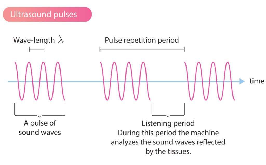
The ultrasound transducer generates short bursts (pulses) of ultrasound waves. Reflected ultrasound waves are analyzed by the machine during the brief pauses between the pulses. Thus, the machine analyzes (“listens to”) reflected sound waves immediately after it emits sound waves (Figure 1).
To create a reliable real-time image of the tissue, the ultrasound machine must overcome the following technical obstacles.
- The ultrasound machine must know which sound waves are reflected and from where they are reflected. Since the sound waves are sent out in pulses and the velocity in the tissue is constant (1540 m/s), the machine can calculate where the sound waves were reflected (i.e the machine can calculate the reflection point). This is done by analyzing the time it takes for the sound to return to the transducer and thus calculating the distance to the structure that reflected the wave. Structures located near the transducer will reflect the sound waves early and thus the time interval will be short. Structures located far from the transducer will reflect the sound waves later and it will take longer to reach the transducer.
- Ultrasound waves reflected from the same structure can reach the different crystals at different time points. To solve this, there is a built-in function, called dynamic focusing, which calculates which ultrasound waves that originate from the same reflection point.
- Reflected ultrasound waves have altered properties (e.g altered amplitude). This is exploited to give the reflected sound waves, based on their amplitude, different nuances on the ultrasound image. The tissues in the ultrasound image are drawn with varying shades of one color (usually gray). This is possible because the vibrations in the piezoelectric crystals, and thus the electric current they send back to the machine, vary with the amplitude of the reflected sound. The stronger the reflections, the higher the amplitude and the whiter the color of the tissue on the ultrasound image.
- Moving structures (myocardium, blood flow) will alter the characteristics of ultrasound waves (e.g. frequency). This is actually exploited to calculate the direction and speed of tissue and fluid movements.
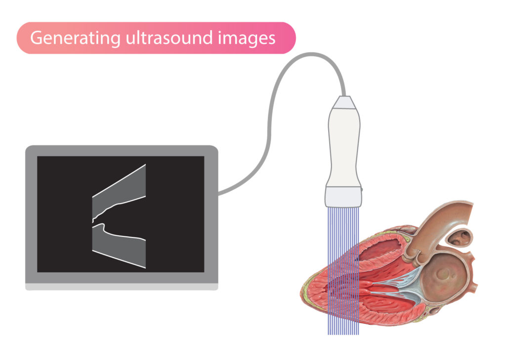
All structures in a medium can reflect ultrasound waves. However, the greatest reflections occur in the interfaces between two media. Hence, in the transition from blood to myocardium, many sound waves will be reflected and this will result in a clearly depicted border zone between blood and myocardium on the echocardiogram. Ultrasound waves will also be reflected as the waves travel through the myocardium, but to a lesser extent, and therefore the myocardium does not shine as clearly on the ultrasound image (Figure 2).
Ultrasound waves are primarily reflected in the interface between media (tissues, fluids, etc) of different density. The greater the difference in density, the more ultrasound waves are reflected. This explains why tissue borders appear as brighter structures on the ultrasound image.
Directing and focusing ultrasound waves
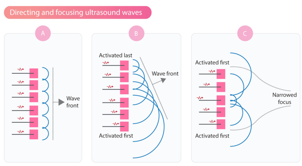
The direction and focus of ultrasound waves can be adjusted by varying the sequence of activation of the piezoelectric crystals (Figure 3). By activating all crystals simultaneously, the resulting sound wave travels in a straight direction (Figure 3A). If activation starts on one side, for example from right to left, then the wavefront will be directed to the left (Figure 3B). If the activation starts at the ends and proceeds towards the center, then the ultrasound beam will be focused as illustrated in Figure 3C.
Modern ultrasound machines include advanced software that handles the activation of thousands of piezoelectric crystals. Using sophisticated software and hardware, it is possible to obtain high-resolution two-dimensional (2D) and three-dimensional (3D) echocardiograms.
Reflection of ultrasound waves
As mentioned previously, ultrasound waves are primarily reflected in the interface between media (tissues, fluids, etc) of different density. The greater the difference in density, the more ultrasound waves are reflected. For example, the difference in density between skin and bone is very large, which explains why most of the ultrasound waves are reflected when they hit bone. Structures located behind bone can therefore not be visualized using ultrasound (since very few sound waves go through the bone). Similarly, the difference in density between the air-filled lungs and the pericardium, explains why much of the ultrasound is reflected on the pericardial surface (which therefore shine brightly on the echocardiogram).
The larger the proportion of sound waves reflected, the fewer sound waves remain to study the rest of the tissue (deeper structures). Air-filled spaces (i.e lung) and hard surfaces (i.e bone) pose a special challenge. It is therefore important to place the transducer and direct the sound waves such that collision with bone and passage through lung tissue is minimized.
When ultrasound waves travel through soft tissues and fluid-filled spaces (e.g ventricular cavity, atria, larger vessels), a relatively small proportion of sound waves is reflected. This is due to the small difference in density within the tissue or fluid.
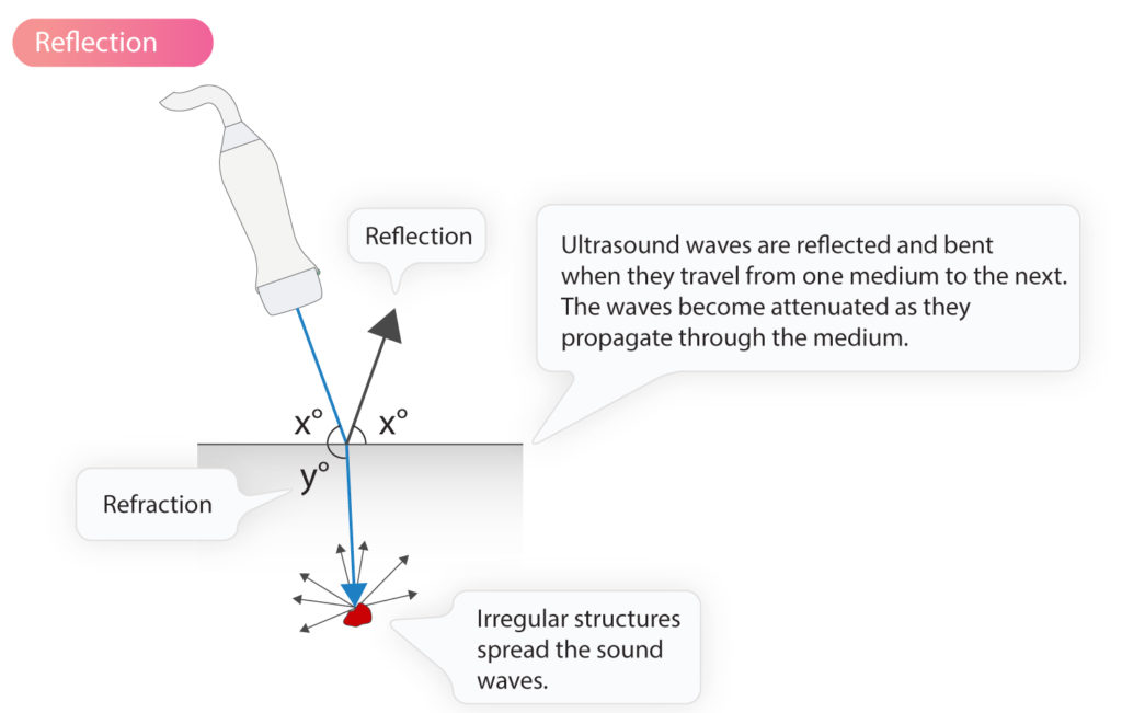
For an ultrasound wave to be reflected at an unchanged angle (compared to the angle of incidence), the object reflecting the ultrasound wave (i.e the reflector) must have a smooth surface, perpendicular to the direction of the sound waves. Human tissues consist of more or less irregular structures, which results in sound waves always being reflected at a slightly altered angle. However, the change in the angle is generally small and most of the reflected sound waves hit the transducer. This type of reflection is called mirror reflection. The ultrasound waves that are not reflected at the interface between two media will continue through the second medium with slightly altered angle, a phenomenon called refraction.
Although most of the reflected sound waves are reflected in the border zone between two media (tissues/fluids), some waves are also reflected during passage through homogeneous tissue, such as the myocardium. Otherwise, the myocardium would not have been visible on the echocardiogram. However, reflections within the tissues are more scattered. The more irregular the structure of the tissue, the more scattered the reflections.
Erythrocytes are particularly good at spreading the ultrasound waves; they spread the waves in all directions. Thus, only a minority of reflections return to the ultrasound transmitter.
Ultrasound waves are attenuated (weakened) as they travel through the body. The attenuation is due to the reflection of sound waves and the transformation of mechanical energy into heat (which is absorbed by the tissues).
Resolution and penetration of ultrasound waves
Obtaining high-resolution ultrasound images is essential for diagnostic accuracy. The image resolution can be defined as the possibility to distinguish two adjacent objects. Studying small structures, particularly moving structures, requires high-resolution images. The lower the image resolution, the more difficult to distinguish smaller and neighboring objects.
The image resolution depends mainly on the wavelength of the ultrasound waves. As discussed previously (Physics of ultrasound) the wavelength is inversely proportional to the wave frequency according to the following formula:
λ = c / f
This implies that high-frequency waves have short wavelengths and vice versa. The shorter the wavelength, the smaller structures will be able to reflect the sound wave and thus become visible on the ultrasound image. Thus, the higher the frequency, the higher the resolution. It may, therefore, seem reasonable to increase the frequency to the limit of the ultrasound machine. However, the penetration of ultrasound waves diminishes with increasing frequency, meaning that high-frequency waves have poorer penetration. Visualization of deeper objects, therefore, requires waves with lower frequency.
Ultrasound waves with low frequency have a long wavelength, which provides lower resolution but better (i.e deeper) penetration. Image quality for distally located objects can thus be improved by using lower frequency; the increase in penetration typically outweighs the loss in resolution.
The maximum resolution is about half the wavelength; e.g a frequency of 2.5 MHz yields a resolution of 0.3 mm. Objects smaller than 0.3 mm are not distinguishable at a frequency of 2.5 MHz.
Axial and lateral resolution
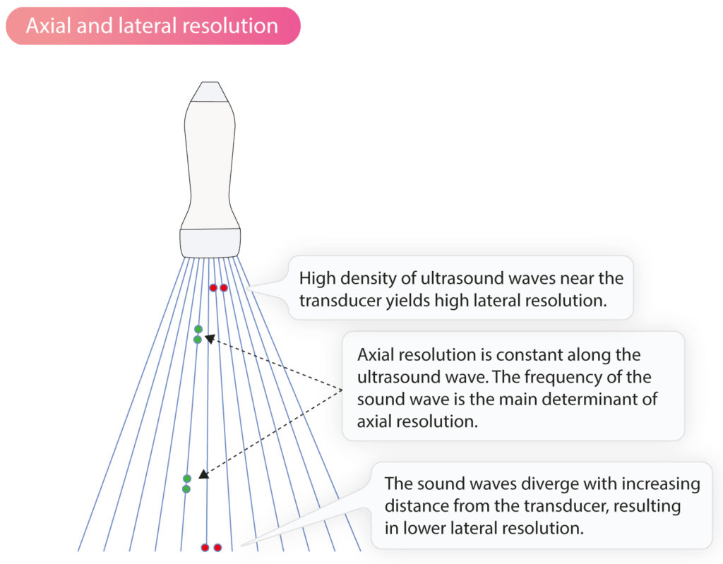
The axial resolution is the ability to distinguish two objects located parallel to the ultrasound wave. This resolution is constant along the ultrasound wave. The axial resolution is fundamentally dependent on the frequency of the sound waves. The higher the frequency the greater the axial resolution.
The lateral resolution describes the ability to distinguish two objects that are perpendicular to the ultrasound waves. This resolution decreases with the distance from the transducer because the ultrasound waves diverge as the distance increases.
Temporal resolution
Temporal resolution (also see Frame rate below) is the ability to describe the movement of objects over time. Ultrasound imaging in general, and echocardiography in particular, requires continuous analysis of reflected ultrasound waves to create a 2D or 3D film. The film is created based on individual ultrasound images that appear one after another. In order to generate a film with high temporal resolution, it is critical to produce individual images rapidly. The time it takes to create one image determines the temporal resolution. The more images that can be produced and presented per unit of time, the greater the temporal resolution.
Fundamental and harmonic imaging
The ultrasound transducer generates sound waves with a specific frequency. This frequency is called the base note. When the sound waves pass through the tissues, the sound waves are deformed which creates harmonics.
Sound waves are deformed as they pass through tissues. When the high-pressure portion of the sound wave (the highest point of the sine curve, see Physics of Ultrasound) encounters tissue with higher density, the tissue will be compressed and the speed of the sound wave is increased. When the low-pressure part of the sound wave (the lowest point of the sine curve) passes through the tissue, the opposite will occur: the tissue expands, tissue density decreases and the speed of the sound wave also decreases.
Thus, the sound wave is distorted as it passes through tissues. This distortion results in the occurrence of sound waves whose frequency is multiples of the base note. These sound waves are called harmonics. Thus, the ultrasound transducer emits waves at frequency of 3 MHz and then sound waves with frequency 6 MHz (second harmonic), 9 MHz (third harmonic), 12 MHz (fourth harmonic), etc, arise. These harmonics are also reflected back to the transmitter. In fact, it is possible to create an ultrasound image using only reflected harmonics. This results in images with improved resolution. Modern ultrasound machines are therefore programmed to primarily analyze reflected harmonics (mostly the first harmonics).
The ultrasound image is created by listening to one harmonic and filtering out all other frequencies (both the base note and all other harmonics). This imaging method is called harmonic imaging.
Harmonic imaging is standard in ultrasound diagnostics and echocardiography. The method makes it possible to send out sound waves of low frequency (allowing deeper penetration of the tissues), but listen to sound waves of high frequency (yielding higher resolution). Harmonic imaging also reduces artifacts in the ultrasound image. The disadvantage of harmonic imaging is that some texture is lost. This is not a significant issue but it may result in heart valves appearing thicker than they really are.
The opposite of harmonic imaging is fundamental imaging, which implies that the machine listens for sound waves at the same frequency as it itself generated. For example, if the transducer emits sound waves at a frequency of 3 MHz, it only listens for reflected sound waves that have 3 MHz. This gives poorer resolution and lower penetration. There are, however, situations in which fundamental imaging is useful.